On the RRTR:
As I began to build out the panel, I leaned on gathering as much information as possible, from as many sources as possible, and then committed to spend the time to getting the panel to best fit the railroad. One thing that sticks out in my mind is that even prototype installations were one-offs; US&S had standard sizes for cabinets, and the relay signals and logic, but fitting that to each railroad meant lots of customization.
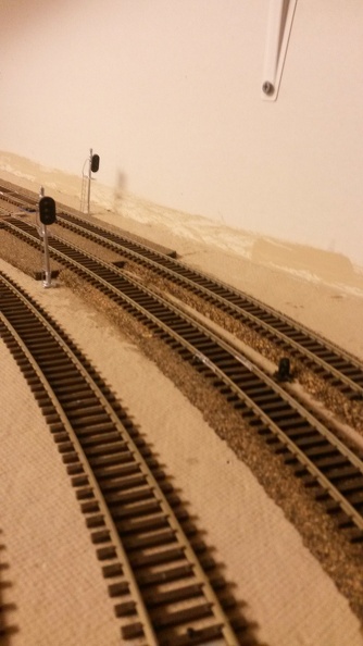
I changed the physical signals on the railroad more than a few times as I got closer and closer to prototype practice and I learned what they would do in certain situations. Here on the east side of the country, most railroads used signaling systems that told the engineer what speed to maintain or reduce to, as the train moved over the physical plant of the railroad. The west part of the country used systems that were more directional in nature; meaning it would tell the engineer that he would be diverging on a particular turnout. This picture to our left shows a fairly late installation on the layout, but none the less, it will need to be changed, as that dwarf in the foreground needs to move elsewhere at this interlocking.
When I built out the panel, I provided fairly simple signaling to my crews - green for clear, yellow for approach and red for stop. Just like in real life, it did not stop folks from running signals and causing some interesting situations, but everybody lived to fight another day. As an example of this, at the beginning of a simple block, I would have a 3 light, Color Position Light (aka CPL) signal. If you think of it as an inverted traffic signal that you'd see on the roads, you have a pretty good idea of what I'm talking about. (And there is a whole story about why red is at the bottom of railroad signals..) For a location where there is a turnout and two blocks begin, I would have a 3 over 3 CPL. E.g. imagine a traffic signal mounted to the top of another traffic signal. This worked ok and my crews got fairly decent about what to do.
Of course, the prototype doesn't do it that way. Each signal will display a single aspect to the train crew. An aspect is a combination of different color lights, (possibly different positions of lights on some railroads - hello PRR fans) that tells the train crew what they should do with respect to their train speed. Should the crew either maintain, reduce to, speed up after they pass this signal or stop?
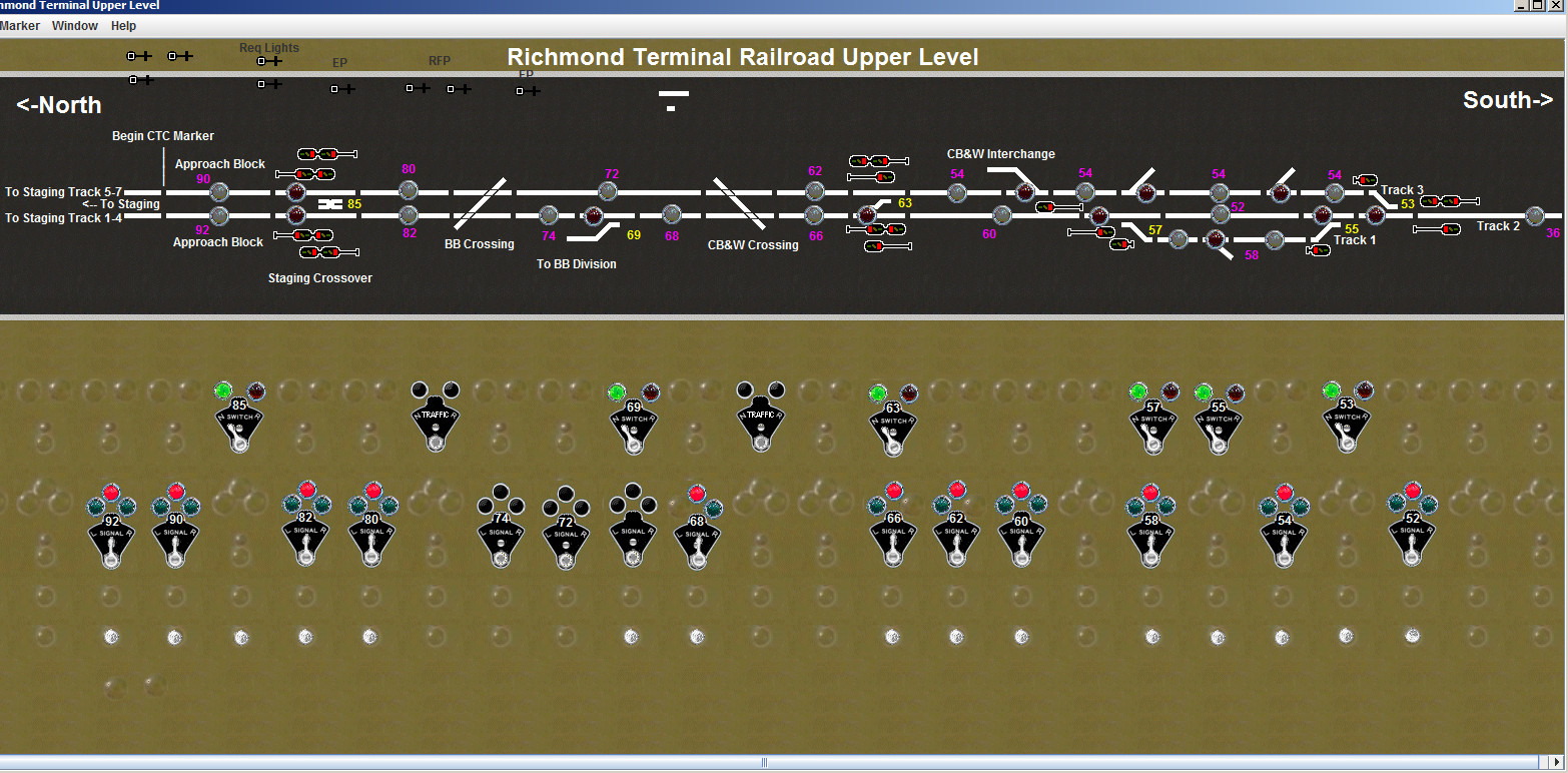
When I built the upper level, I was out of spots on the signal driver board I was using; and was thinking about investigating other alternatives, as I discussed in a blog post here. This started my quest to begin building out aspect based signals. Using the SignalMan board from RR-Cirkits made it easy on the upper level and I used JMRI to make the Digitrax based signals give me the same output via the signal mast functionality.
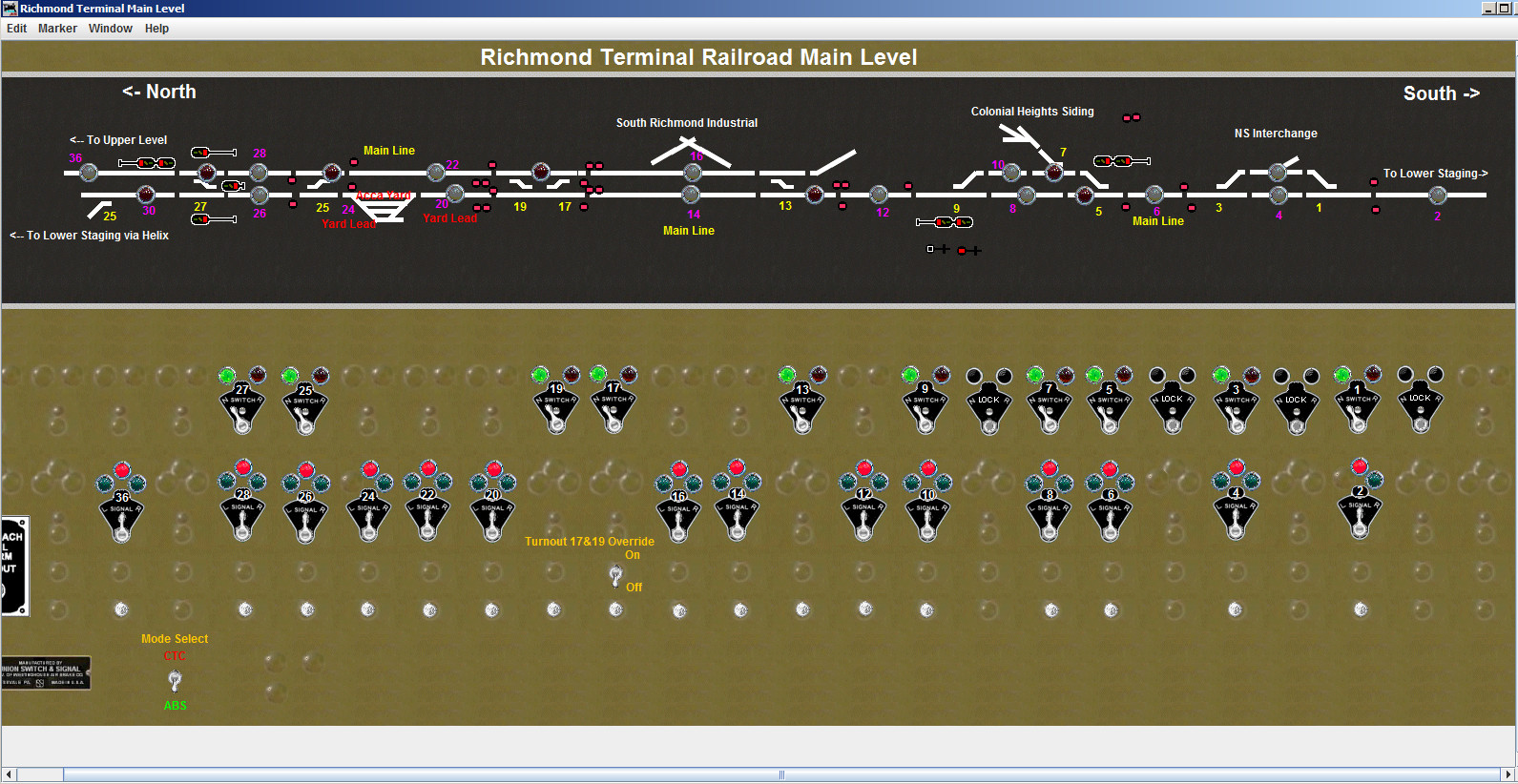
One thing that my panels have that most panels did not in real life is that the signals were NOT displayed. I choose to display the aspects to help me and my dispatchers understand what was happening on the layout. Eventually, I plan to have a script or switch I can use to hide the signal aspects and display the icons only, so the panel looks just like the prototype.