Layout Details, Version 2
The major paradigm hasn't changed, as version 2 is a multiple deck, shelf style layout. The par benchwork width is about 9", but there are both narrower and wider sections. The narrowest is 4" (just enough for doubletrack on a tangent) while the widest will be 30" in Acca.
The room size and shape has let me include some important features that were not present on V1. The two major features that show on V2 are the wye at Acca and having Acca be double-ended, just like the prototype. I also get a chance to have a full wye at Doswell, where before I could only simulate it.
The track plan has evolved during the build as potential issues came to light. These plans have been printed very large so if you attempt to print on 8x11 paper, don't expect to be able to tell much. I recommend just looking at them full size and scrolling around unless you can print at 11x17 and larger.
Lower Level Track Plan and Upper Level Track Plan. These PDFs might not be great quality; the print to PDF software for whatever reason has started to be a bit balky.
Still using the homasote on plywood plan and doing that through out to speed construction, as well as simplify the engineering tasks that go into building the benchworl and structure. I decided that in many cases, I over engineered and spent too much time on details that didn't matter on V1.
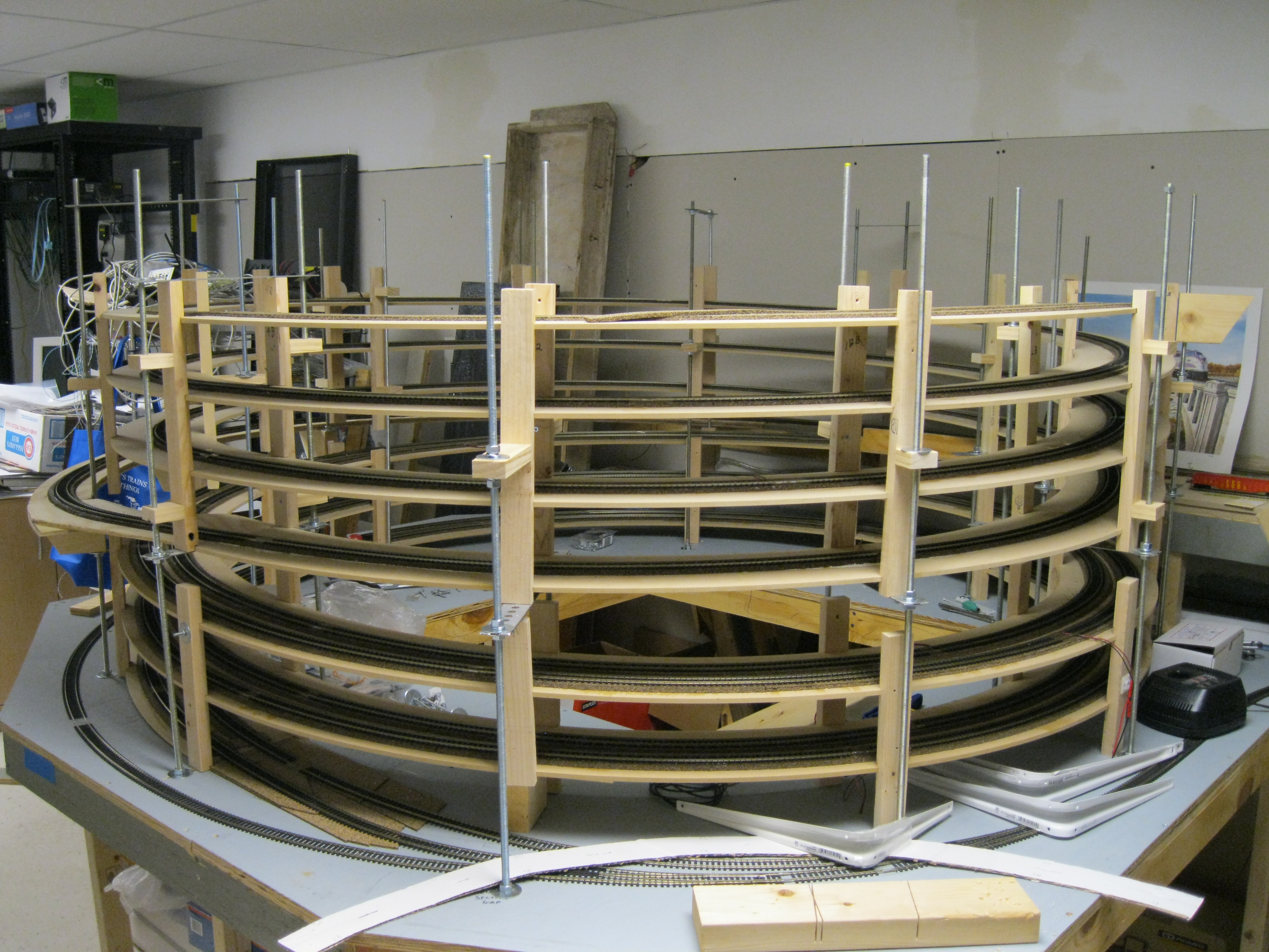
Here on V2, I am building from the top down. As I only have two decks, this allows me the freedom to work unencumbered under the top deck to install signals, switch machines and all the wiring that goes along with those features.
Mainline track is on cork, glued to homasote. I'm cutting my cork from rolls that are made for flooring underlayment, which is significantly cheaper that buying the box of 25 strips and it allows me to cut pades to the most effecient shape and size as needed, again allowing me to save material.
Layout Details, Version 1
The layout was a multiple deck, shelf style layout. Normally the benchwork area was less than 12" wide. Many spots were 6" or less. At the widest point, Acca Yard, it did bump out to 24". Like most modelers, I had to compromise in what would fit and what would work well when it comes to operations, so the classification tracks are single ended, rather than double like the prototype.
The track plans should be considered "baseline" type of documents, as the as-built railroad differs from the track plan in a couple of spots. Hopefully they give enough insight that the reader can understand the size and scope of the layout.
Main Level Track Plan Upper Level Track Plan
The benchwork was mostly built from 3/4" plywood; I ripped the sheets of it down to 3" wide strips that I then used to provide joists and other support framework, since this was cheaper (and certainly straighter) than dimension lumber. One thing I discovered is that the big box stores (Home Depot and Lowe's) sell 3/4" plywood that 1. isn't 3/4" and 2. Isn't consistent from 1/16 to 1/4 from a nominal 3/4" inch thick. Fun times occur when you try to match up your subroadbed and find issues like this.
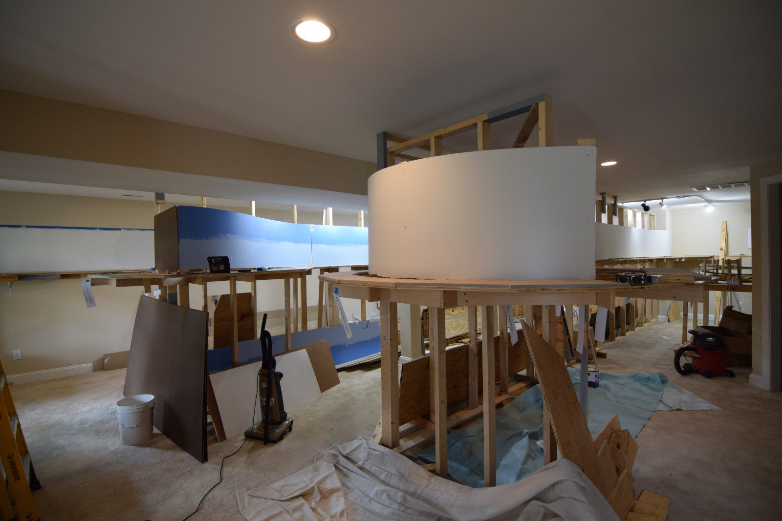
I started benchwork with the lowest level staging yard, which is 33" or so from the floor at track level. I build the benchwork somewhat like modules or dominoes in 8 foot long sections. I made an attempt to make things somewhat modular to make it easier to remove when the time comes to sell this house. As time went along, I moved away from the truly modular style and just built things in place once I realized that trying to fit a shelf style layout into a different room than what it was built in was probably a fool's errand and that I should save the time spent in engineering modular solutions and use it elsewhere. The upper level reflects this change, as it is homasote on top of 3/4" plywood with offset joints. (Something else learned during construction.)
When I first started laying track, I used the Woodland Scenics roadbed product, Track-bed, instead of cork, thinking that cork was "old" technology. Turned out that cork is easier to deal with and, as a big bonus, holds spikes very well, making track changes or reuse very easy. The track-bed, does not hold spikes, meaning you have to glue track down. This means that a good portion of the mainline will end up in the dumpster when I move anyway, no matter how modular I made it.
Note: Almost all the track on the railroad south of Acca that was glued (which was 95% plus of what was south of Acca, including the South staging yard) ended up in the trash. I figured that I put about 2 boxes (25 pieces, each) of C83 Atlas flex, plus 2 cases of Atlas C100 flex, plus 19 turnouts (Atlas, a mix of #6 and #8s), into the landfill, which means that I've got to replace that for the new layout, which means my train budget will take a multiple hundred dollar hit.
What did I learn from this for the second version? Spike track down.